Thursday, November 21, 2013

Network Protocols

Networks run on many different protocols that offer many different functions. I have previously discussed protocols such as TCP and UDP which control the communication sessions between two systems. There are many more protocols that enable a network to function as a whole. Some of these are discussed next.

Address Resolution Protocol

The ARP protocol works at the Data Link Layer and provides addressing capability. Whereas the transport layer uses the IP protocol for addressing, the data link layer uses what's referred to as the Media Access Control (MAC) address. The MAC address is programmed into the NIC by the manufacturer and is a combination of an ID unique to the manufacturer, and an ID that the manufacturer assigns. When systems communicate on a network, the data layer needs to be able to add the MAC address for the intended recipient. For it to be able to do this, it must be able to look at the IP address the transport layer used and resolve it to a MAC address. This is done through the ARP protocol. ARP maintains a table, or cache, that lists which IP address corresponds which MAC. If there is no MAC listed for an IP address, ARP can send a broadcast packet requesting the MAC address of whatever system has a certain IP.

A common attack against ARP is known as ARP cache poisining. When ARP was designed, there was no security built into the protocol. The vulnerability lies in that ARP does not authenticate where other ARP packets come from. Because of this, any system can send an ARP reply, unsolicited, to another system claiming to have a certain IP address. The target will accept this packet and update it's ARP cache. From then on, anytime a packet needs to be sent to that IP address, it will be instead routed to the attacker. This is a simple way to perform a man-in-the-middle attack.

Dynamic Host Configuration Protocol

DHCP is a protocol that can assign systems IP addresses in real time. DHCP functions over UDP and is commonly implemented as a service on routers. DHCP leases out IP addresses from a set range and maintains a table of currently leased out IP addresses. This prevents any two systems from accidentally receiving the same IP address which would cause a conflict. Each IP address that is assigned is given a lease time. When the time expires, the system must renew its IP address. The steps to receive an IP address via DHCP are listed below:
  1. A client computer connects to a network and sends a DHCP discover packet.
  2. The DHCP server responds with a DHCP offer packet, which gives the client an available IP address and details configuration settings.
  3. The client responds with a DHCP request packet confirming its acceptance of the settings.
  4. Finally, the DHCP server responds with a DHCP ack packet which acknowledges the client's acceptance and includes the lease period of the address.

Internet Control Message Protocol

ICMP is used for testing connectivity and sending messages. Perhaps its most well know implementation is through the ping utility. When administrators wish to test if they are able to connect to a system, they may ping it to see if they get a reply. When ping is used, an ICMP echo request packet is sent. If the intended recipient receives the packet, it will reply with an ICMP echo reply packet. This packet can tell the sender that the message was received and provide information about the connection, such as response time. ICMP is also commonly used by routers to gain information about the state of connections. When a problem occurs with a route, ICMP can be used to send information to surrounding routers letting them know about the issues. Routers also use ICMP to send information about packets that were not able to reach their target.

There are a couple of attacks that use ICMP to cause damage. One such attack is the ping of death. ICMP packets are normally set to not exceed 65,536 bytes. If an attacker crafts a packet larger than this common size, the receiver may freeze or become unstable, bringing the system down. Another attack is know as the smurf attack. This attack takes advantage of the fact that most system actively listen for and respond to ICMP traffic. An attacker can craft an ICMP echo request packet with an address of a system that they wish to attack. This packet is sent to all the other systems who, upon receiving it, send an ICMP echo reply to the target system. The target then receives so many ICMP packets at once that it doesn't know what to do and goes down.

Simple Network Management Protocol

SNMP was developed in the late 1980's to aid in network management. The protocol functions with a manager/agent relationship. The manager is the server portion which periodically polls the agents to request new information. Each agent is assigned a group of objects that it is to watch and maintain information about. This information is tracked in a database-like structure called the Management Information Base (MIB). An MIB is a logical grouping of related objects that contain data used for specific management tasks and status checks. The manager will periodically poll the agents requesting the information in the MIB. This gives the administrator a good way to monitor the network as a whole.

Saturday, November 16, 2013

Network Topology

The physical arrangement of computers and devices is called network topology. The topology of a network determines the manner in which a network is physically connected and shows where resources are located. It is possible that while a network has a certain physical topology, it may be logically connected in a different way. For instance, a network may be physically laid out as a star topology but be logically controlled as a ring. The type of topology that is used will depend on what configuration makes the most sense for the resources involved and the context of the network. In reality, company networks are made up of many smaller networks that may vary greatly in topology.

Ring topology

In a ring topology, devices within the network are laid out in a closed loop. Each system is part of this loop and is connected to the rest of the network through the device on either side of it. The transmission link is unidirectional in a ring topology, so data flows only in one direction. Because there is no central device to which the rest of the network connects, a packet must travel through each device along the ring until it reaches it's destination. In a simple network, this could be a source of failure because if one system goes down there is no way for information to continue flowing through the network. In modern systems, there are redundancies in place to prevent this from happening.

Bus topology

A bus topology uses a single cable as a backbone for the network. Nodes are connected to this cable through drop points and have the ability to look at each packet as it travels along the cable. When a device transmits to another on the network, the packet gets placed on the cable and is examined by each node until the one it's addressed to sees it and pulls it. Because the cable serves the entire network, it is a possible single point of failure.

Star topology

In a star topology, each node is connected to a central device such as a switch. A dedicated link exists between each node and the central device, so devices are not as dependent on each other as they are in other networks. Aside from the central device going down, a node going out will not negatively impact the network. This topology also requires less cabling than other topologies. Most networks are based on a star topology today because this type of network is more resilient than ring or bus.

Mesh topology

The final topology is mesh topology. In a mesh topology, all systems are connected to each other. This topology offers a large amount of redundancy because every node is connected to every other node, but a large amount of cabling is required, and it can be a real mess to handle. A partial mesh topology would be a network where there exists many connections between nodes, but not every node is connected to every other system. The internet is an example of a partial mesh network.

The diagram below illustrates the different network topologies.

Friday, November 15, 2013

The format of network communications

Every data transmission has three fundamental characteristics. Format (analog vs. digital), synchronization (synchronous vs. asynchronous), and how communication sessions are handled (baseband vs. broadband). These characteristics are discussed next.

Analog vs. Digital

To transfer data from one location to another, a signal must be created. This signal serves as the medium by which data is transported. There are two signaling formats; analog and digital. Analog signals are used by technologies such as radios and have a wave shape. The wave shape enables an analog signal to express an infinite amount of values that flows continuously. Digital signals, on the contrary, are discreet and a voltage within a certain range will represent either a 0 or a 1. As a comparison, think of how an analog watch is different than a digital watch. With an analog watch, hands are used to convey the current time, and, if the watch has a second hand, the time is constantly flowing. A digital watch simply read the time at that moment. There is no movement or flow involved.

For the purposes of networking, digital signals are the preferred format. Computers have always processed data in 0's and 1's. When telecommunications networks carried only analog signals computers required a modem to modulate and demodulate analog signals. With new advances this is no longer needed. Digital signals are also able to travel for much further distances before they degrade. These are a couple of the reasons why telecommunications and other networks are moving to all digital formats.

Asynchronous and Synchronous

When two machines need to share data over a network, this is much like two people having a conversation. As people speak with each other, there are natural pauses between sentences and thoughts. Theses gaps allow the other to process what has been said, and it helps form a natural rhythm to the conversations. We also have rules for written language. Periods and commas can show when a thought ends, and spaces seperate words into individual units. These rules allow us to synchronize our communications. Just as we have grammar rules to synchronize our conversations, so do computers. Asynchronous and synchronous describe two different sets of rules for how computers communicate with one another.

In asynchronous mode, start and stop bits are used to distinguish when a character starts and ends. This is done for the whole message so that the receiving system is sure to correctly interpret the message. This is just like the earlier example of inserting spaces between words so that a person can easily read them. In synchronous communication, there are no start and stop bits used. Instead, the data is transmitted in a continuous stream. To synchronize the transmission, a clock pulse is used. This is similar to when we verbally talk and I use pauses to form a natural rhythm. For synchronous transmission to be used, both systems must be using a synchronous protocol such as high-level data link control (HDLC). This protocol allows the system to interpret the information it's sent. Asynchronous transmission happens through a protocol known as asynchronous transmission mode (ATM).

Baseband and Broadband

Baseband and broadband refer to how communication sessions are handled in the physical transmission media. A baseband technology uses all of the communication channel for its transmission. A broadband technology divides the channel into sub-channels so that multiple transmissions can occur simultaneously. For instance, a coaxial cable TV is a broadband technology that delivers multiple television channels over the same cable.

There is an important distinction that just because a technology could transmit multiple signals on one channel, doesn't mean it is broadband. Unless there are specific rules for how the channel will be divided, it is still a baseband technology. As an analogy, think of a large one lane highway. Because there is only one lane through which to travel it is baseband. But if we go and paint white lines down the middle (put in rules for dividing the channel) the highway now supports more traffic and is broadband.

All of these characteristics come together to make up a transmission technology. For instance, WiFi is an analog transmission that uses ATM for synchronization and is broadband because it divides set frequencies into channels. These characteristics exist for every transmission media and are important to understanding how data is transmitted.

Physical Layer

The bottom layer of the OSI model is the physical layer. This is where the bits hit the wire. Depending on the transmission technology, the frames will be encoded to match. Each transmission technology (Ethernet, Token Ring, FDDI) has it's own standard for how the data should be transmitted. The protocols at the above layer know what kind of technology the network is transmitting on and tells the physical layer what voltage and signaling scheme should be used. The network interface card serves as a bridge between the data link layer and the physical layer. It's the NIC's responsibility to physically encode the frames.

Wednesday, November 6, 2013

Data Link Layer

We are nearing the bottom of the OSI model now. Layer 2 is the data link layer. As the packet moved down the protocol stack, information has been added that tells the recipient what kind of data the packet contains, if it's part of an ongoing conversation, where this packet falls in the sequence of total packets, and if this packet is indeed intended for them. Now it is time to translate the packet to the proper format for the technology that it will be broadcast over. This is the job of the data link layer.

LAN and WAN technologies can use different protocols and mediums for transmission. Each has it's own specifications for how data should be packaged for transmission and for how it interprets electrical signals. If a computer is communicating over an Ethernet network then the headers must be a certain length with the flags properly set. If the specifications of the transmission technology are not followed the receiving system will not be able to properly interpret the data.

The data link layer handles preparing a packet to be transmitted. The layers above it do not know how the packet is going to be transmitted and do not need to be concerned with it. The data link layer will add the necessary information to the packet headers, change the data into the necessary format, and fix sequencing of received packets. If there are transmission errors then the data link layer will also alert upper-layer protocols.

The data link layer is divided into two functional sub-layers. The top of the these two sub-layers is the Logical Link Control (LLC). This sub-layer works with the network layer directly above it. The logical link control handles flow control and error-checking. So if a packet is received out of sequence or there is an error, the LLC will alert the network layer to take action. Below the LLC is the Media Access Control (MAC) sub-layer. This is where a packet is translated to the necessary format for the technology it will be placed on. The technology at the MAC layer knows if the network is an Ethernet, Token Ring, FDDI, or something else and will place the final headers and convert the data to it's appropriate electrical signal. Note that once the data link layer applies the last header and trailer the unit of data is now called a frame.

Some protocols that work at the data link layer include Point-to-Point Protocol (PPP), ATM, Layer 2 Tunneling Protocol (L2TP), FDDI, Ethernet, and Token Ring. Each network technology (Ethernet, FDDI, ATM, Token Ring) also defines the compatible physical transmission type (coaxial cable, twisted pair, fiber) and electrical signaling and encoding. The MAC sub-layer understands these requirements and tells the physical layer what type of electrical signal to create.

Network Layer

Moving down the OSI model to layer 3 we have the network layer. This layer's main responsibility is addressing and routing packets to their proper destination. To accomplish this, the network layer adds information to the header of packets that details what computer a packet is intended for. The packet is then passed on to the lower layers where it will eventually be placed on the wire. As a packet traverses a network, each system examines the header of the packet to see where the packet is addressed for and how to route it. The protocols at this layer will also help in routing the packet to it's destination. Routing tables are built and maintained which detail the layout of the network. Some routing protocols are able to determine the best path for a packet to take based on multiple factors including distance and transmission rate. So when a packet needs to be sent the routing protocol will check it's routing table, add the necessary information, and send it on its merry way.

Protocols that work on this layer do nothing to ensure delivery. They rely on the protocols of the transport layer to provide that functionality (if the protocol used by that layer even provides that option). Protocols at the network layer are solely concerned with routing and addressing. The most well known protocol at this layer is the Internet Protocol (IP). As the name suggests, this is the core protocol that much of the internet functions on. Other protocols include Internet Control Message Protocol (ICMP), Border Gateway Protocol (BGP), Routing Information Protocol (RIP), Open Shortest Path First (OSPF), and Internet Group Management Protocol (IGMP).


Transport layer

The transport layer is layer 4 of the OSI model. It falls right below the session layer and right above the network layer. As previously discussed, the session layer is responsible for creating, maintaining, and tearing down connections between applications on two systems. The transport layer performs a similar functionality, but on a larger level. Where the session layer works with two applications, the transport layer manages connections between two computers. When two computers need to communicate, they look to the transport layer to establish the connection.

There are two types of protocols that function at this level; connection-oriented protocols and connectionless protocols. Connection-oriented protocols are concerned with maintaining a persistent connection between the two systems. These protocols will undergo a process known as a handshake to establish parameters that guide the connection. During the handshake, the communicating computers will agree on how much information will be sent at a time, how integrity will be checked once the data is received, and how to detect if a packet was lost along the way. Connection-oriented protocols provide error-checking and are able to retransmit packets that were lost or damaged. Well known connection-oriented protocols include Transmission Control Protocol (TCP) and Secure Sockets Layer (SSL).

Connectionless protocols do not concern themselves with error-checking or agreeing on how much or at what rate to transfer data. These protocols will simply send the data without first trying to contact the recipient. The result is that the data may or may not reach its destination and the sending system has no way of confirming this. This sounds like a big deal, but there is much data that gets sent that is not crucial, and if a few packets occasionally do not make it to their destination it is not a big issue. Developers will often use a connectionless protocol because it carries significantly less overhead since there is no need to create and maintain a connection or provide error-checking. The most well known connectionless protocol is User Datagram Protocol (UDP).

Tuesday, October 29, 2013

Session Layer

The session layer is right below the presentation layer in the OSI model. The session layer's responsibilities are centered around allowing applications on different systems to communicate with one another. When an application on one system needs to speak to another, a session must be established. Once a session has been established, the applications are able to freely share data. The session layer provides the functionality of establishing, maintaining, and removing the session. Once the conversation is over, the session layer will remove the session and release any resources it was using. A similar analogy is making a phone call. If I want to speak with you I will call your phone to initiate a session. Once you answer the session is active. We can then talk back and forth. At the end of the conversation we hang up and the resources that were committed to our session are now released for others to use. This is known as dialog management.

When the session layer sets up the connection, there are three types of connection it may use. Each affects how data will flow from one machine to the other. These modes are:

  • Simplex - Communication takes place in one direction
  • Half-duplex - Communication takes place in both directions, but only one application can send information at a time
  • Full-duplex - Communication takes place in both directions, and both applications are able to send information simultaneously
It may seem like it would make the most sense to just always have a full-duplex connection because this would allow both applications to easily communicate, but this isn't the case. In computing we always have to be mindful of the resources we are consuming, so if we can manage with less it's best to do so. A simplex connection requires less overhead and is perfect for any operation where only one system needs to be able to send information. Similarly, half-duplex is great for if each system only needs to periodically update one another.

There is often times confusion about how the session layer is different from the transport layer. The transport layer is responsible for establishing and controlling connections between systems. This is very similar, but the difference is the level they work at. The transport layer is concerned with computer to computer communication, while the session layer is concerned with application to application communication.

Some protocols that function at this level include Structured Query Language (SQL), NetBIOS, and remote procedure call (RPC).

Monday, October 28, 2013

Presentation Layer

Layer 6 of the OSI model is the presentation layer. This layer works right below the application layer and is primarily responsible for putting data given to it by the application layer into a format that other computers using the OSI model can understand. It provides a common way for systems to display and use information despite what application the user may be using on their system. For instance, suppose that Jack creates a document on a Windows machine using Microsoft Word. He then wants to send this file to Jane who uses uses Open Office instead of Word. To achieve this, the application layer passes the file on to the presentation layer which decides the proper way to encode it; in this case, it chooses American Standard Code for Information Interchange. The message continues to move down through the other layers, across the wire, and up through the model on the end system. When the presentation layer on Jane's machine receives the message it looks at the headers placed by Jack's system. It sees that the information is in ASCII format and tells the application layer which decides what program is appropriate for opening this type of file.

The presentation layer is focused solely on the syntax and format of the data and pays no attention to the meaning of any of the data. It translates the format that an application uses to a standard format that is used when transferring information over a network. When a program saves a file, such as an image, a format must be specified, such as GIF, or JPEG. The presentation layer adds information to the file that tells the computer how to display the file and process it. This way if the file is later sent, the receiving computer will also have instructions on how to properly display the file.

The presentation layer is also responsible for compression and encryption of files. If a compressed or encrypted file is to be sent over a network, the presentation layer will write information about how it is compressed of encrypted to the header of the packet. Again, this tells the receiving system's presentation layer what process was used to compress or encrypt the file and it can pass that information on to the application layer. In the event that the receiving system doesn't know that compression algorithm or file format, the file will be displayed with an unassociated icon.

Sunday, October 27, 2013

Application Layer

The application layer is not the applications a user runs on their system. Rather, this layer is made up of protocols that support these applications. When a user is performing some action with an application and then wants to send this data as a message, application layer protocols are called on to package the data (using headers and footers) and pass the data on to the next layer (in this case, the presentation layer). The message will continue to move down the OSI model as each layer performs its duties on the message, until it eventually reaches the target system and moves in reverse through the model. When the target system's application layer receives the message, it looks at the headers and footers that were placed there by the user's application layer and processes the data in the correct manner.

As another example, say you want to mail a letter to your friend. You write the letter and hand it to me, the application layer. I take the message and put it in an envelope and pass it on to the other layers which will eventually add the address and name of the recipient. When the recipient receives the letter, she removes the envelope (strips off the headers and footers) and is presented with your message. This is similar to how the application layer functions.

Some protocols that function at this layer include Simple Mail Transfer Protocol (SMTP), Hypertext Transfer Protocol (HTTP), Line Printer Daemon (LPD), File Transfer Protocol (FTP), Telnet, and Trivial File Transfer Protocol (TFTP). Each of these has an application programming interface (API) that defines how they can be called by an application. When an application, such as a mail client, wants to send a message it will call on a protocol; in this case, SMTP. The API of SMTP says how the information must be presented to the protocol for it to do its job. After the mail client makes a call to the SMTP API, SMTP adds its information to the user's message and passes it on to the presentation layer.

OSI Model

The OSI model was developed by the ISO in an attempt to standardize the way in which systems communicate across networks. The hope was to create a standard protocol set which would allow the product of any vendor to be able to network with other vendor's products. While the protocol set did not catch on, the model did. At the time of the OSI model's creation, the TCP/IP protocol suite was already in place as a widely used networking protocol. While TCP/IP has it's own model which is still commonly used today when examining and understanding networking issues, the protocol suite has become an integral part of the OSI model.

The OSI model is made up of seven layers. Each layer represents a different step in communicating over a network. At each layer, there are a set of protocols that operate to achieve that layer's responsibility. The objective of the OSI model is to outline how the protocols at each layer need to function so that they can work with systems that may be developed by other vendors. This concept is known as an open network. An open network architecture is one that no vendor owns, and if implemented, it provides a standard way of operating. It is this open network design that lets a computer that uses an Intel processor communicate with another that uses AMD.

The seven layers of the OSI model, moving from the top to the bottom are: Application, Presentation, Session, Transport, Network, Data link, and Physical. Each layer has a different function when creating a
message to be sent over a network. When a system needs to create a message to send, it begins at the top of the model and works down. Each layer adds information to the message as it travels down the model. At each stop the message grows in size. When the receiving system gets the message, the message moves in reverse up the model. As it moves up the model, each layer removes the information that was added by it's counterpart layer on the other system. Once each layer removes the data that pertains to it, it passes the message on to the next layer. This process where layers and protocols communicate with their counterparts across systems is known as encapsulation. Encapsulation is based on the idea that a layer only needs to know how to do it's job and how to pass the message on to the next layer. The session layer is not concerned with how the physical layer is going to put the electrical signals onto the wire, and vice versa.

Each layer has different responsibilities and functions it performs, as well as a format it expects the message to be in. Each layer also has a connection point, or interface, that allows it to communicate with three other layers: 1) the layer above it, 2) the layer below it, and 3) the same layer on the target machine. A layer provides control functions by adding information to the message in the form of headers and footers on the data packet. This tells the corresponding layer on the target machine how the message is to be handled.

The benefit of encapsulating the responsibilities of these layers is it allows products from different vendors to work together within the single model in a predictable manner. If a vendor designs a protocol for the session layer that is based on the OSI model, other vendors, and consumers, can be certain it will function properly with other open system protocols.

Wednesday, October 23, 2013

Surveillance Devices

Visual recording devices can play an important part in physical security. Their presence can discourage would be attackers, provide the ability for one person or system to monitor multiple areas simultaneously, and provide a log of events for an area. A commonly used system is closed-circuit TV (CCTV).

CCTV systems are made up of cameras, transmitters, receivers, and monitors. The camera captures the data and transmits it to a receiver which then displays the data on a monitor. Today's systems surpass older models that only allowed one feed to be displayed on a monitor at a time. Today, a monitor can show feeds from multiple cameras so that a security guard can see more than one environment simultaneously. Data captured by the camera is also often recorded on a drive for record and later review. Most modern CCTV cameras today also use light-sensitive chips call charged-coupled devices. This chips are what convert the light received into electrical signals. What makes the chips advanced is that they include infrared light which is normally beyond the scope of human eyesight. This allows for more granularity and detail in the resulting image.

An important consideration for CCTV cameras is what type of lens will you need. There are two main types used: fixed focal length and zoom (varifocal). The focal length affects how objects are viewed on a horizontal and vertical basis. Short focal length lenses provide a wider-angle view, while long focal length lenses provide a more narrow view. This angle determines what size the images seen by the camera will be and how much of an area the camera can view. So if you want to be able to monitor a wide area at once, a short focal length lens is most appropriate. If the camera is installed in a smaller area, a long focal length lens is best. A fixed focal length lens comes in a size such as wide or narrow and is stationery. A zoom lens is adjustable, however, and can be used to view something closer and will refocus.

The next characteristic of lenses is depth of field. Depth of field refers to what portion of the image is in focus when shown on the monitor. Depth of field is affected by the size of the lens opening, the distance of the subject, and the focal length of the lens. The depth of field increases as the size of the lens opening increases, the subject distance increases, or the focal length decreases.

Lighting also plays an important role in CCTV. Cameras have an iris lens which controls how much light enters the camera. A manual iris lens has to be adjusted manually and is best suited for an environment with a steady light supply. An auto iris lens has the ability to self adjust as the environment light changes such as outside.

The last consideration is that of mounting. A fixed mounting is stationery and cannot move in response to security personnel commands, whereas a camera with PTZ capabilities provides pan, tilt, and zoom features.

As you can see, there are many considerations for installing a CCTV system. To get the best results, a thorough assessment of the environment and needs of the organization should be done. CCTV systems can become very expensive quickly so it is important to prioritize what features are needed where.

Fire Detection and Suppression

Fire can be one of the most damaging physical events. Damage to systems, buildings, and people can cost a company great deals and be a tragedy. Because of this it's very important that fire safety be taken seriously. It's also why regulations exist that ensure a minimum amount of protection against fire. This post will discuss the different technologies used for fire detection and suppression. Equally important is fire prevention which includes proper training and ensuring the correct supplies are accessible in case of emergency, though this will not be discussed.


Fire detection

Fire detection systems come in two base varieties, manual and automatic. Manual systems are the red pull boxes that many people are familiar with. These systems are activated by a person once a fire is detected. Automatic systems are able to sense heat or smoke in a variety of ways. When a fire is detected the system will sound an alarm before triggering a suppression system.

A common type of smoke detector uses a photoelectric device to test the air for smoke. In one variety, a beam of light originates at an emitter and ends at a receiver. The system monitors the intensity of the light and sounds an alarm if the light becomes obscured. Another variety draws in air surrounding the detector and tests the air quality with a photoelectric device.

Heat activated systems monitor the temperature of the environment and watch for noticeable changes. These systems can be set to sound an alarm if a certain temperature is reached (fixed temperature) or if the rate of change exceeds a predefined limit (rate-of-rise). Rate-of-rise systems can provide an earlier alarm than fixed temperature systems but can also be the source of more false alarms.

It is important that fire detection devices be installed in all the proper areas and not just in obvious places like offices and hallways. Many office buildings have dropped ceilings and raised floors where wiring is ran. There should be detection devices installed in both of these to ensure an early alert in case of an emergency. Additionally, smoke or heat can often gather in ventilation systems before being dispersed to the surrounding areas, so there should be detection devices installed in these areas as well.

Fire suppression

Not all fire is equal. There are four types of fire and each requires a certain type of suppression device. Use the wrong one, and you could end up making the fire bigger/stronger rather than extinguishing it. The table below summarizes the classes of fire and the appropriate suppression method.
Fire Class Type of Fire Elements of Fire Suppression Method
A Common combustible Wood products, paper, and laminates Water, foam
B Liquid Petroleum products and coolants Gas, CO₂, foam, dry powders
C Electrical Electrical equipment and wires Gas, CO₂, dry powders
D Combustible metals Magnesium, sodium, potassium Dry powder
Foams are mainly water-based and are designed to float on top of a fire and prevent any oxygen from flowing to it. Gas, such as halon or FM-200, mixes with the fire to extinguish it and is not harmful to computer equipment. Halon has been found to damage the atmosphere, however, and is no longer produced. CO₂ gas removes the oxygen from the air to suppress the fire. It is important that if CO₂ is used there be an adequate warning time before disbursement. Because it removes the oxygen from the air it could potentially endanger people's lives. CO₂ is often used in unmanned facilities for this reason. Dry powders include sodium or potassium bicarbonate, calcium carbonate, or monoammonium phosphate. The first three interrupt the combustion of a fire, and monoammonium phosphate melts at a low temperature and smothers the fire.

Water sprinkler systems are much simpler to install than any of the above systems but can cause damage to computer and electrical systems. It's important that an organization recognize which areas require which types of suppression systems. If water is to be used in an environment that contains electrical components, it's important that the electricity be shut off first. Systems can be configured to shut off all electrical equipment before water is released. There are four main types of water systems:

  • Wet pipe - Wet pipe systems always contain water within the pipe and are usually controlled by a temperature sensor. Disadvantages of these systems include that the water in the pipe may freeze, and damage to the pipe or nozzle could result in extensive water damage.
  • Dry pipe - Dry pipe systems employ a reservoir to hold the water before deployment, leaving the pipes empty. When a temperature sensor detects a fire, water will be released to fill the pipes. This type of system is best for cold climates where freezing temperatures are an issue.
  • Preaction - Preaction systems operate similarly to dry pipe systems but add an extra step. When empty, the pipes are filled with pressurized air. If pressure is lost, water will fill the pipes, but not be dispersed. There is a thermal-fusible link on the nozzle that must first melt away before the water can be released. The advantage of this system is it gives people more time to react to false alarms and small fires. It is much more effective to put out a small fire with a hand-held extinguisher than a full spray system.
  • Deluge - Deluge systems have their sprinkler heads turned all the way open so that greater amounts of water can be released at once. These types of systems are not usually used in data centers because of this. 

Tuesday, October 22, 2013

Perimeter Security, Part II

Locks

Locks can be used to secure access points throughout the location. Padlocks may used on the outer gate, mechanical locks on the building doors, and keypads on interior doors. These various types of locks provide different levels of security and have different features. It's important to understand that locks aren't truly a deterring factor in security, however. Many attackers see locks as a puzzle and a challenge; not a reason to give up.

Mechanical locks

There are two main types of mechanical locks: warded lock, and tumbler lock. The warded lock is a basic padlock. Inside of a warded lock, there is a spring-loaded bolt with a notch cut into it. The key fits into this notch and slides the bolt from the locked to the unlocked position. Additionally, there are wards, or metal projections, that the key is cut to fit around, as illustrated. Warded locks are the cheapest kind of lock because of their lack of sophistication and are also the easiest to pick.

Tumbler locks have more pieces and parts and can prove a more secure option. Within a tumbler lock, there are multiple metal pieces that have to be raised to a certain height before the bolt can be turned. The key for the lock will have the correct sequence of notches cut into it to allow it to raise each tumbler to the appropriate height. There are two common types of tumbler locks: pin tumbler and wafer tumbler. Pin tumbler locks (pictured left) use spring loaded pins inside of the lock. Pin tumbler locks are the most commonly used tumbler lock. Wafer tumbler locks are the small, round locks you usually find on file cabinets. They use a flat disk instead of a pin and are not as secure.
Combination locks require a combination to be entered which aligns internal wheels before being unlocked. These are the locks that you likely used in high school.

Programmable locks

Programmable locks, or cipher locks, are keyless locks that use a number pad to control access. The lock requires a specific combination to be entered and may incorporate other security devices such as a biometric scan or key card. Programmable locks cost more to install, but give the ability to change the code, lock out certain sequence patterns, and have codes for emergency situations such as if a person were under duress. In this situation, entering the emergency code will open the door while also triggering a remote alarm. Other features of programmable locks are:
  • Door delay - If a door is held open for a given time, an alarm will trigger to alert personnel of suspicious activity
  • Key override - A specific combination can be programmed for use in emergency situations to override normal procedures or for supervisory overrides
  • Master keying - Enables supervisory personnel to change access codes and other features of the cipher lock
  • Hostage alarm - If an individual is under duress and/or held hostage, a combination he enters can communicate this situation to the guard station and/or police station

Perimeter Security, Part I

The first line of defense for any organization is it's perimeter control. As mentioned before, physical security should be applied in a layered approach. If a criminal is able to circumvent outer controls such as fences and locks, there must be more controls inside to delay the attacker until a response can be made.

Fences

Fences can serve as an effective outer physical barrier. They are likely to only delay the most determined attackers, but they give a strong psychological impression that a company is serious about security. When installing fencing, many companies choose to also place shrubs or bushes in front to improve aesthetics. Vegetation can greatly improve the look of the fence, but also may damage the fence over time, so proper maintenance is key.

When choosing a fence there are multiple factors to consider. Height, gauge, and mesh size are very important qualities of fencing. Fences in the three to four foot height range will stop only the most casual attackers as these can be easily jumped. Six to seven foot fences are considered too high to easily climb, and eight foot or higher fences are used when you're really serious about security. Often with these higher fences, barbed or razor wire will be strung along the top to really convince people that trying to climb it would be a bad idea.

The gauge of the fence refers to the thickness of the wire that makes up the body. The higher the gauge number, the thinner the wire. Below is a table summarizing the most common sizes:
  • 11 gauge = 0.0907-inch diameter
  • 9 gauge = 0.1144-inch diameter
  • 6 gauge = 0.162-inch diameter
The mesh size of the fence refers to how much distance is between the wires. A smaller mesh size makes it more difficult to climb or cut. Common mesh sizes are 2 inches, 1 inch, and 3/8 inch.

One last consideration when installing fences is that the posts and wire frame must be installed deep enough into the ground to prevent anyone from trying to dig underneath it.

Saturday, October 19, 2013

Crime Prevention Through Environmental Design

Crime Prevention Through Environmental Design (CPTED) emphasizes the philosophy that crime can be prevented or deterred through strategic design which influences human behavior. The ideas of CPTED were first developed in the 1960's and continue to play an important part in structure design to this day. CPTED is used when developing office buildings, neighborhoods, campuses, towns, and cities. It addresses landscaping, entrances, lighting, paths, and traffic circulation patterns. The core idea of CPTED is that human behavior can be influenced by the design of an environment and used to reduce crime.

Natural Access Control, Surveillance, and Territorial Reinforcement

Natural access control is the guidance of people entering and leaving an area by using elements such as paths, lighting, and even landscaping. For instance, cars can be prevented from encroaching on a pedestrian area through the use of bollards. These bollards can also emit light which illuminate the path for pedestrians and help to usher them to or from an entrance. Additional items like hedges may help to restrict people from leaving the intended path.

Natural access control can also be used to deter the misuse of non-normal entrances. A building may have a side door that is used for special circumstances, such as emergencies. This door could be a prime target for criminals because it may be away from normal traffic flow. To combat this with CPTED, the organization could consider placing a bench within visibility of the door which would encourage people to sit and gather, thus deterring any illegal acts. Clear lines of sight are used frequently in CPTED to dissuade criminal activity and create natural surveillance. Because of an absence of hiding places, criminals are less likely to target the area.

Organizations will also frequently try to create clear areas of ownership. CPTED teaches that if legitimate users have a sense of ownership about their area, they will be more likely to defend it if necessary. Users will also be more aware and skeptical of suspicious activity. The goal is to make any would-be criminals feel uncomfortable and as if they may be monitored at any point. Territorial reinforcement can be achieved through the use of fences, natural boundaries through landscape, paths for walkers, or areas to play. All of these things give a sense of ownership to the space.

Target Hardening

I will mention briefly that CPTED is distinct from target hardening. Target hardening includes activities such as installing locks, security systems, and cameras. These efforts may also deter crime, but do so through different measures. Target hardening often restricts the use of an area through physical and artificial barriers, whereas CPTED emphasizes opening up areas to encourage public use.

Monday, October 14, 2013

Physical security

We're now moving on from security architecture and design and into the next domain - physical security. Physical security is made up of the people, processes, procedures, technology, and equipment used to protect the resources of a company. In a good physical security program, these components are employed through a layered defense model, that is, an attacker must navigate through a series of defenses in order to gain access to an asset. This concept will be discussed in greater detail in future posts.

Physical security deals with a different set of threats than information or computer security. These threats can be grouped into these broad categories:

  • Natural environmental threats: Floods, earthquakes, storms and tornadoes, fires, extreme temperature conditions, etc
  • Supply system threats: Power distribution outages, communications interruptions, and interruption of other resources such as water, gas, air, filtration, and so on
  • Manmade threats: Unauthorized access (both internal and external), explosions, damage by disgruntled employees, employee errors and accidents, vandalism, fraud, theft, and others
  • Politically motivated threats: Strikes, riots, civil disobedience, terrorist attacks, bombings, and so forth
Additionally, another unique aspect of physical security is the concern of life safety. Unlike in information or computer security, threats to physical security can be potentially deadly. Necessarily so, life safety becomes the primary concern whenever developing a physical security program.

Planning a physical security program

Planning a physical security program shares many of the same steps and considerations as planning other security programs. Management must decide what level of risk is acceptable for various assets so that it can determine the appropriate level of security to apply. A grocery store will not require the same level of physical security as a data center. To decide what level of security is appropriate, a risk analysis is performed which identifies threats and measures their potential business impact if exploited. It is important to additionally consider and legal or regulatory obligations that a company must meet in this step.

Once a team has been formed and a risk analysis has been performed, a physical security program can be developed that fits the organization's needs. Specifics as to what technologies, procedures, or equipment can be implemented will be discussed in the future, but the general goals of the security program are as follows:
  • Crime and disruption prevention through deterrence: Fences, security guards, warning signs, and so forth
  • Reduction of damage through the use of delaying mechanisms: Layers of defenses that slow down the adversary, such as locks, security personnel, and barriers
  • Crime or disruption detection: Smoke detectors, motion detectors, CCTV, and so forth
  • Incident assessment: Response of security guards to detected incidents and determination of damage level
  • Response procedures: Fire suppression mechanisms, emergency response processes, law enforcement notification, and consultation with outside security professionals
As you can see, a physical security program must address both preventing and responding to incidents.

Finally, after a physical security program has been developed and implemented, it must be monitored and evaluated. It is possible to measure and determine the effectiveness of the program through a performance based approach. Under this approach, metrics must be developed to measure how well the program is working. The goal is to increase the performance of the program and decrease the risk to the company in a cost-effective manner. Possible metrics include:
  • Number of successful crimes and disruptions
  • Number of unsuccessful crimes and disruptions
  • Time between detection, assessment, and recovery steps
  • Business impact of disruptions
  • Number of false-positive detection alerts
  • Time it took for a criminal to defeat a control
  • Time it took to restore the operational environment
  • Financial loss as a result of a crime or disruption
Tests such as fire drills or penetration tests can help to evaluate weaknesses in the security program and identify areas of improvement.

Saturday, October 12, 2013

Systems evaluation methods

Evaluating a system can be a very lengthy and tedious process. The goal of the evaluation is to determine how effectively a system enforces the security measures that the vendor claims it has. The result is a rating describing the assurance level of the system. This rating describes to what degree the system can be trusted to enforce it's security measures. This is valuable for when someone is looking to purchase a new system and needs to know how reliable the system's security is.

When a system is submitted for evaluation against one of the methods that will be described soon, a lengthy process begins which includes tons of paperwork and a full analysis of the system. The examination includes dissecting, at a very fine level, how various components of the system work independently and together. Areas examined include the trusted computing base, access control mechanisms, kernel, reference monitoring, and protection mechanisms.

There are three evaluation methods that will be discussed. These are The Orange Book, the Information Technology Security Evaluation Criteria (ITSEC), and the Common Criteria methods. Of these three, the Common Criteria is becoming the industry standard, and was, in fact, developed to be so.

The Orange Book

The Orange Book, more formally known as the Trusted Computer System Evaluation Criteria, was developed by the U.S. Department of Defense to evaluate operating systems, applications, and different products. It is known as the Orange Book due to the orange cover that it sported. The Orange book breaks it's assurance rating into four division, A - B - C - D, with some of the divisions having more than one class in it. Classes with a higher number represent a higher assurance rating. So C2 is greater than C1, and B1 is greater than C2. Criteria on which systems are evaluated breaks down into seven areas outlined as follows:
  • Security policy - The policy must be explicit and well defined and enforced by the mechanisms within the system.
  • Identification - Individual subjects must be uniquely identified.
  • Labels - Access control labels must be associated properly with objects.
  • Documentation - Documentation must be provided, including test, design, and specification documents, user guides, and manuals.
  • Accountability - Audit data must be captured and protected to enforce accountability.
  • Life-cycle assurance - Software, hardware, and firmware must be able to be tested individually to ensure that each enforces the security policy in an effective manner throughout their lifetimes.
  • Continuous protection - the security mechanisms and the system as a whole must perform predictably in different situations continuously.
Each division and class is cumulative, meaning to meet a higher rating, a system must also meet all requirements for lower divisions and classes. The criteria remains the same, all that changes is how closely components are examined and how well they are designed and enforced.

TCSEC was first introduced in 1985, and was the first methodical set of standards developed for evaluating computer systems. It was retired in December 2000.

Information Technology Security Evaluation Criteria

The Information Technology Security Evaluation Criteria (ITSEC) was the first attempt my many European countries to develop a standard for evaluating computer systems. With the ITSEC, a different approach was taken to separate the ratings of functionality and assurance. Each is given an individual rating on separate scales.

When functionality is examined, a system is tested to see how well it delivers the promises it's vendors make. If a vendor claims a firewall will effectively manage state, it should be shown that it does in fact do this. The design of functions can vary widely from product to product so while two systems may both provide the same functionality, they may do so in very different manners. This raises the need for the second rating of assurance. Assurance is examined to determine how trustworthy the process is that delivers this functionality. Assurance is a degree of confidence in the system to perform it's function.

When a system is rated it is given a grade that reflects it's functionality and a separate grade for it's assurance. The table below shows a mapping of these ratings to their functional equivalent on the Orange Book scale. As you can see, there is an additional set of ratings in the ITSEC that aims to address consumer needs not addressed by the Orange Book.

ITSEC TCSEC
E0 = D
F1 + E1 = C1
F2 + E2 = C2
F3 + E3 = B1
F4 + E4 = B2
F5 + E5 = B3
F5 + E6 = A1
F6 = Systems that provide high integrity
F7 = Systems that provide high availability
F8 = Systems that provide high data integrity during communication
F9 = Systems that provide high confidentiality (like cryptographic devices)
F10 = Networks with high demands on confidentiality and integrity

Common Criteria

The goal of the Common Criteria was to address the flaws of both the Orange Book, and the ITSEC. The Orange Book's fatal flaw was a narrow scope that concerned itself with only the confidentiality of a system. The ITSEC made progress on this, but used a confusing, complex rating system that allowed vendors to mix and match ratings.

To address this, the Common Criteria developed a straight forward scale that addressed both confidentiality and assurance. Under Common Criteria, products are given an Evaluated Assurance Level (EAL). The lowest EAL rating is EAL1 and the highest is EAL7. The lower levels of the EAL scale examine functionality; does the product deliver on it's promises? The higher levels involve more methodical testing that examines the assurance level of the product's functionality.

Where Common Criteria really sets itself apart though, is in it's protection profiles. These profiles outline the need for a product and the likely threats it will face. It takes into account any assumptions made and what type of environment the product will function in. These profiles allow for more targeted testing, and provides greater feedback to customers who want to know if a product is right for them and their network.

Common Criteria is the current globally recognized standard.

Tuesday, October 8, 2013

State machine models

A computer's state can be described as a snapshot of the system at any point in time. All of the current instances of subjects and objects, and how they are interacting, are a part of the state. When developers are building an operating system they may wish to implement a state machine model. To do this, the developers will examine all of the ways that subjects can interact with objects and how the state of the system may change as inputs are accepted by objects. Every time an object accepts an input, a state transition occurs. If, after examining every possible association and interaction, it is decided that every state transition is concurrent with the security policy of the operating system, then the system is secure and effectively enforces a state machine model. Note that for the purposes of this post, models will be discussed in an abstract manner, while in reality there is a large amount of mathematics involved during development to prove the effectiveness of the model.

A system that successfully implements a state machine model will, by definition, always be in a secure state. The system will boot into a secure state, execute transactions and commands securely, and will even fail in a secure state. It is critical that the system be able to fail in a safe way so that if an error or illegal operation occurs it is able to save itself without leaving itself vulnerable.

Two very well known state machine models are the Bell-LaPadula Model, and the Biba Model.

Bell-LaPadula Model

The Bell-LaPadula model is a state machine model that focuses on maintaining confidentiality. It often serves as the basis for mandatory access control (MAC) operating systems as are used by the government. Because its primary focus is confidentiality, the Bell-LaPadula model uses security labels along with an access matrix to enforce security. It is a multilevel security system because users with different levels of access use the system. There are three rules that are core to the framework of the model:
  1. Simple security rule - A subject cannot read data within an object that resides at a higher security level ( the "no read up" rule).
  2. * - property rule - A subject cannot write to an object at a lower security level (the "no write down" rule).
  3. Strong star property rule - For a subject to be able to read and write to an object, the subject's clearance and the object's classification must be equal.
The first rule is easy enough to understand. If you are give the classification of "secret", and a file is labeled "top secret", you do not have the proper clearance to read it. The purposes of the second rule are to prevent a person from writing highly classified information to a lower level, thus damaging the confidentiality. The final rule ensures that a subject has both the proper clearance and the need to know to access an object. While I may be given "top secret" clearance, I may not have a need to know about a missile program and therefore should not be able to access files associated with it.

Biba Model

The Biba model is similar to the Bell-LaPadula model in that it also has three rules which enforce what states the system may enter. Where the models differ, however, is their focus. While Bell-LaPadula is concerned with maintaining confidentiality, Biba is focused on maintaining integrity. The goal of the Biba model is to ensure that data of high integrity is not corrupted by data of low integrity. This would be useful in systems such that handle financial data, or healthcare information. The three rules for Biba are as follows:
  1. * - integrity axiom - A subject cannot write data to an object at a higher integrity level (referred to as "no write up").
  2. Simple integrity axiom - A subject cannot read data from a lower integrity level (referred to as "no read down").
  3. Invocation property - A subject cannot request service (invoke) of higher integrity.
The first two rules control how data may flow between different integrity levels.  You would not want your high integrity data, or "clean" data, to be mixed with lower integrity "dirty" data. These not only prevent users from traversing integrity boundaries, but processes as well. A process at a lower level should not be able to write data to a higher level. The invocation property also states that a lower level process may not invoke a process higher than it. This means that processes cannot make use of any tools or services that have a higher integrity ranking, they may only use what is below them.

Monday, October 7, 2013

Operating System Architecture

There are three broad designs for operating systems that I'm going to talk about. These are monolithic architecture, microkernel, and hybrid microkernel architecture. The key differences among these is how the operating system handles separating which processes run in user mode and which run in privileged, kernel mode. As will be shown, the decision has a strong impact on security and performance.

Monolithic architecture

In a monolithic architecture, the kernel is made up of all the operating system processes. This means that any service provided by the operating system (file management, interprocess communication, I/O management, etc) is run in a privileged state. Essentially, the operating system behaves as a software layer between the user applications and the hardware. This is efficient for the processor as it requires very few mode transitions to be made. A mode transition must be executed anytime a process with a different PWS (privilege word setting) is executed. It takes time to make this transition, so avoiding them is generally good for performance.

There are, however, several problems with this design as well. Processes within a monolithic architecture often communicate on an ad hoc basis which provides little for access control. It also results in very complex code which can make debugging or updating very difficult. And because the operating system works directly with the hardware, it can be very difficult to port the operating system to other systems.

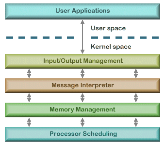
There is one monolithic architecture model that helps to tackle some of these problems. That is the layered operating system model. In a layered operating system model, all of the operating system's processes are still part of the kernel, but they have been compartmentalized and have structured ways of interacting.

The image to the left shows the general structure of a layered operating model. Each layer has the ability to communicate with the layer directly above and below it. This provides a more structured way of communicating, and provides data hiding which means instructions and data at various levels do not have access to the instructions and data at other levels. And since the code is now more modular, it is much easier to upgrade or perform maintenance. There are still security concerns with this model, however, because so much code is given kernel privileges.

Microkernel and Hybrid Microkernel Architecture

Under the microkernel model, much of the code was stripped from the kernel and placed within the user space. This increased security because it meant that less code would be able to run in privileged mode. All that was left in the kernel space was key operating procedures such as memory management and interprocess communication. The overall goal of the microkernel model was to limit the processes that run in kernel mode to improve security, reduce complexity, and increase portability.

Engineers found that the microkernel suffered a major setback in performance, however. Because so many of the processes were now in user space, the CPU would constantly have to perform mode transitions. In response, the hybrid microkernel architecture was created.

In a hybrid model, the microkernel still exists. And as before, it is responsible for carrying out interprocess communication and memory management. The other operating system processes that had previously been relegated to user space were moved to an area contained within the kernel known as executive services. These services, such as file management, I/O management, power management, and so on, now operate on a client/server model. This means that whenever a user application wants to make use of one of these services, they must request it using the service API. The service will then carry out the request and return the result when finished. A sample hybrid microkernel model is below. This picture illustrates the architecture of the Windows NT operating system.

Virtual machines

For this post I wanted to try something a little different and get away from the purely text / diagram driven content. I decided to make a video using Screenr (www.screenr.com) and show off some virtual machines. If I had more time I could have probably done something more interesting with the machines, but it's still nice to have that visual aspect. Rich data is fun! So here is a link to the video I ended up creating. Below it, I'm going to highlight a couple of key security considerations about virtual machines. Enjoy!


Key takeaways

I briefly touched on some of these in the video, but it's worth writing out as well.
  • Virtual machines can be used to consolidate work from several underutilized machines to one machine.
  • Virtual machines can allow a company to upgrade it's systems, but still run legacy applications.
  • Virtual machines can provide secure, sandbox environments for testing and debugging.
  • Virtual machines can provide the illusion of hardware, or hardware configuration that you do not have.
  • Virtual machines can allow you to run multiple operating systems at once.
  • Virtual machines can isolate what they run, preventing damage to the host system or other environments.

Saturday, October 5, 2013

Buffer overflows

Buffer overflow is one of the more well known attacks, especially among the tech crowd. It is an attack that targets the memory stack of an application with the purpose of either running it's own source code or altering the way a program runs. Because the target of this attack is the memory of a system, I'll begin by giving a brief introduction to memory management.

Memory management

A computer's memory is made up of several different types of memory that are used for various purposes. I won't go into heavy detail here, but these different types include cache, random access memory (RAM), and read only memory (ROM). Cache memory is a high speed read/write memory used to store values for a temporary amount of time, often between operations performed by the processor. Most often, if a value is going to be needed several times during a process it will be stored in cache memory. RAM is another type of memory used for temporary storage. RAM is significantly larger than cache and is used for read/write activities by the operating system and applications. Both RAM and cache are volatile memory, meaning that when they lose their power they lose any data they were storing. ROM is a non-volatile type of memory used for permanent storage of data (until you want to erase or overwrite it) which takes significantly longer to read and write to.

When a program or the operating system wants to access memory, an address has to be loaded into the processor. Memory addresses, as used by the operating system, are completely sequential. This works well for the operating system because it can easily say, "oh, you want to run notepad.exe? That program is stored in memory location 0x84B2." The difficulty arises when applications want to access memory. A developer cannot know where their program will be stored in memory, or what memory addresses will be available. To solve this problem, applications use what's called virtual memory. Virtual memory allows an application to say, "store this value at space 0", which in reality is memory address 0x2A91. A memory management program is employed to map the logical addresses (the address an application uses) to the absolute addresses (the address the operating system uses).

Buffer overflows

A buffer is an allocated segment of memory. When an application is performing a process that accepts user input, it will set up a buffer to store the value of that input. If the application fails to check the input, a value that is too large for the buffer may be passed, causing the application to overwrite memory outside of the buffer which previously held program instructions or data. This may be done for the purpose of causing havoc or attempting to run another program of the attacker's choosing.

So how exactly can overwriting some memory segments lead to an attacker being able to run a program? To understand this, we need to look at how buffers are set up. When an application sets up a buffer, it creates what's called a stack. The first thing the application places on the stack is a pointer to it's address in memory so that when the process is finished it can return control to the application. On top of the stack pointer the application writes the data passed as variables. The process that the stack is passed to then works from the top, taking the data off as it goes, until it reaches the stack pointer at the bottom which tells it where to return control.

The danger comes when values passed as inputs aren't checked to ensure they fit within the buffer. If a value that is too large is passed, it can overwrite the stack pointer. At this point, if the attack has been crafted correctly, a new stack pointer can be placed at the bottom which sends control to the attackers program that is loaded in the stack. To successfully create a buffer overflow, the attacker has to be able to view how big a stack is and where in memory it resides. If an attacker can figure this out, they can write an exploit for the application.

If developers want to prevent buffer overflows, the simplest protection is secure coding practices. Inputs given by users or other applications should always be checked to ensure they fit within the buffer. Additionally, safe versions of functions such as strcpy (which does not validate input) should always be used.

Tuesday, September 24, 2013

A crash course on the CPU, operating system, and process control

As we move into discussing security architecture and design in computers it's important to have a basic understanding of how the CPU and operating system handle process control. This function forms the basis for how all commands and instructions are carried out. To say what follows is a simplistic version would be an understatement. Entire books are written on the subject and dive much deeper than I ever could.

The CPU (central processing unit), if you didn't already know, is essentially what makes a computer, a computer. It is the brain of the entire machine. It carries out every line of instruction necessary for applications and programs to run. Within the CPU are several components that work in harmony to control the flow of data and carry out the instructions passed to it.
The core of the CPU is the ALU (arithmetic logic unit). This is where the actual instructions are carried out. Because a computer can only perform one instruction at a time, there is a control unit put in place to synchronize the requests from applications with the ALU. As the ALU performs the instructions, it is sometimes necessary to load a temporary value into a register for later retrieval. When the CPU is ready to store a value for a longer period of time, it transfers the data along the bus to memory.

Whenever a new program is launched from within the operating system, a process is created to manage the code associated with the program. A process consists of the instructions that need to be sent to the CPU and any resources that the operating system dedicates to the program. Before a process runs on the CPU, the control unit checks the setting of the program status word (PSW). The PSW declares if the process is trusted or not. Most processes outside of the operating system will be run as untrusted which restricts their access to critical system resources.

The operating system is in charge of controlling how processes access the CPU. Every process is either in a state of running, ready, or blocked. Running means the process is currently being executed by the CPU; ready means the process is ready to be executed; and blocked means the process is waiting on input from somewhere else before it can proceed. In the early days of computing, poor process management was a sinful error that resulted in lost CPU time because many times a blocked process would remain running on the CPU. Because the CPU is what runs the entire machine it is important to allocate work as efficiently as possible. Today, operating systems have been designed to maximize CPU efficiency by using process tables. A process table holds an entry for every current process that describes the processes state, stack pointer, memory allocation, program status, and the status of any open files. The stack pointer is like a placeholder that tells the CPU where the next line of code to perform is.

Making it work in harmony

In the past, a computer would have to perform an entire process at one time and wait for it to release the resources it was using before it could move on to the next task. With the creation of preemptive multitasking, this problem was eliminated. Operating systems now have the ability to recognize when a process is blocked and force it to release any resources it is using. As described above, the operating system has also greatly improved at scheduling processes. Operating systems have become much more sophisticated about preventing processes from accessing memory outside of their initial declared area and can now prevent a process from consuming too many resources and possibly creating a denial of service attack.

Another great improvement has been in thread management and multiprocessing. When a process wants to perform an action, such as printing a file, a thread is generated. The thread contains instructions on how to carry out the requested action. In computers with more than one processor, these threads can be passed to the soonest available processor, thus maximizing the efficiency. When an operating system is able to distribute threads and processes evenly across the processors available this is known as symmetric mode. There also exists asymmetric mode where one processor may be dedicated to only one process, and all other threads are passed to another.